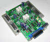
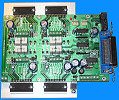
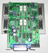
H2 4D CNC Controller
4D, kompact, bipolar, micro-step stepping motor controller
Main technical features (PCB V2.0):
- Step/Dir system, controlled through the LPT port, stepping motor controller,
- 4D (with 4 motors), compact build-up,
- 2-phase, bipolar, micro-step motor control,
- Micro-step values, selected by jumpers: 1; 1/2; 1/8; 1/16,
- Power-output with maximum 35V, 3.5A DC for each motor,
- Mixed mode current decay with PWM regulation,
- Silent holding path operating mode,
- Maximum 100kHz stepping frequency,
- Software controllable motor-rest,
- 4-range, jumperable, motor current regulation,
- 5 input ports (prepared to use end position and digitallable switches),
- 1 relay output (one-pole, maximum load 230V, 3A),
- 2-bit TTL expansion port,
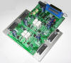
- Build-up that needs only one power supply voltage (with integrated switching digital power supply),
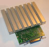
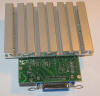
- Protection against overheating,
- Installed cooling,
- Two-sided, partly SMD PCB
CNC control softwares that can be used:
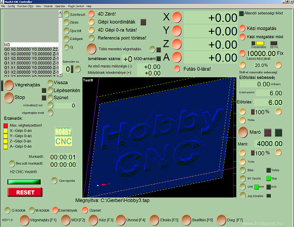
- Mach3 CNC (Win2000, XP) [recommended],
- TurboCNC (DOS),
- WinPC-NC (XP),
- CNCGraf (DOS),
- JediCut,
- GMFC,
- CeNeCe,
- Stealth Plane Works: FoamCutter,
- etc.
 |
 |
 |
 |
 |
 |
 |
 |
|
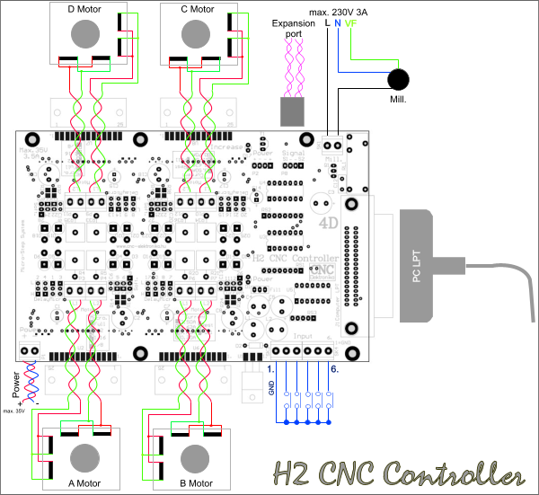
1 stepping motor can be connected to each motor-driving channel (A; B; C; D). Within the motordriving channel, the serial or parallel connection of stepping motors is not recommended. Maximum 5 independent push-button, switch, endposition sensor can be connected to the input port of the controller. The inputs are of Schmitt-trigger type, protected by diodes and contain an internal pull-up resistor of 1 kOhm. Their state are inverted and fed to the PC through the LPT port. Its function is entirely determined by the CNC software running on the PC. A device (e.g. milling machine motor, cutting thread, etc.) can be directly driven (or can be switched) through the relay output. The relay provides a one-pole separation (in case of applying a device, which needs 230 V, a 2-pole auxiliary relay must be applied). The Signal connector is a 2-bit, TTL type output expansion port. This is also of Schmitt-trigger type and inverting looking the signal from the PC side. It can be used to control the fifth axis, (as a Step/Dir output), for a Charge-Pump circuit, frequency changing revolution control (of PWM type), or for a relay expansion output. Its operation is entirely determined by the CNC controlling softwares. A standard LPT cable (printeer cable) must be used between the PC and the Controller. The use of a good-quality shielded cable (its maximum length is 3m) is recommended. The controller needs only one power supply voltage, that of the power supply voltage of the motor. It generates all the voltages that are needed for the electronics. This voltage does not need to be stabilised, only the rectification and filtering is needed. Further information about the design of the power supply can be found in the following. The cooling of the controller must not be blocked, in case of placing the unit in a case, application of a fan may be necessary. It is recommended to apply a fan running at 24 V, and it can be operated from the 24 V AC coil of the transformer. |
|
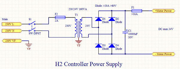
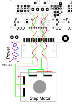
Power supply: A The controller needs only one power supply voltage. It does not need to be stabilised, only rectification and filtering is necessary. The allowed voltage range is 12-35V DC. Exceeding 35V may lead to damaging of the controller. It is recommended to use an insulating safety transformer of 230/24V AC voltage, with a rectifying bridge of minimum 20A and with a capacitor of minimum 10 000 uF. It is also recommended to apply a delayed action fuse of 10A between the power supply and the controller. |
 |
 |
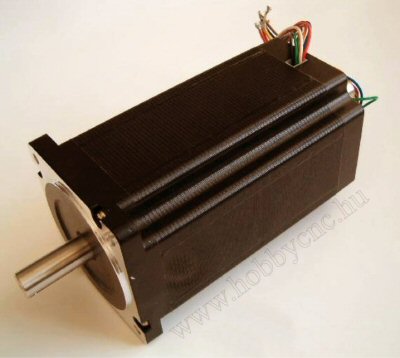
The controller has a 2-phase bipolar motor power output, therefore all types of 2-phase motors can be used. So that the highest possible revolution number could be achieved and because of the micro-step stepping, it is recommended to use bipolar motors with the possible lowest base-voltage. The base-voltage of the motor is the voltage, which is indicated on the data-sheet as the voltage of the coil. The most optimal drive can be achieved if the power supply voltage of the controller is held at 30-35V and the base-voltage of the bipolar motor applied is under 3V. If the motor is a 8-wire type (universal), then parallel connection of the coils is recommended.
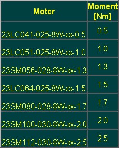
Recommended types of stepping motors:
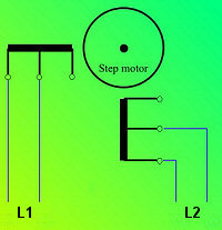
In case of bipolar motors the matching phase-ends must be connected to the L1 and L2 terminals. The phase order does not count, as the rotation direction can be changed within the CNC sofwares. The EMI noise produced by the motors can be substantially reduced by pairing the matching motor-coil ends, therefore their pairing is strongly recommended. Take care of the short circuit-free connection of the wires.
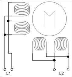
| Zapojenie univerzálnych 8 vývodových motorov: | |
|
|
|
|
| A | B |
There are substantial differences between the 2 modes of connection.
Mode A : at lower speed values a torque of about 20% higher than that of normal can be achieved (twice as much windings are excited), but the available maximum speed value is substantially smaller (because of the twice as much inductivity value and that of the base volatge). The inductivity and base voltage of the motor is twice as much as that of the specification. The current to be adjusted is the nominal current of the coil.
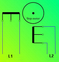
Mode B : all specifications are the same as those of the oroginal ones (higher speed values, nominal torque values). The current to be adjusted equals with the value indicated on the data-sheet. It does not count which coil-end is connected to the middle end to the controller, (it influences only the rotation direction). This is the preferred mode of connection.
Adjustment of the motor current:
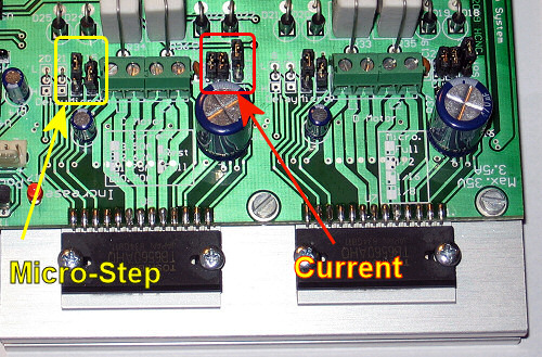
The motor current values for each axis can be adjusted by setting 2 jumpers to one of 4 positions. The jumpers for each axis can be found in the Current field (2 pieces of double jumpers).
The current-rest of a given axis can be determined by the No 3 terminal jumper with the notice "Soft." . In "Rest" position the motors will be down-regulated in standing position (down to 0.7A), supporting by that the better cooling of the motors and that of the controller. This down regulation is emitted when the lowest current value (0.7A) is adjusted. The down-regulation is performed by the CNC software, therefore the correct set-up in the software is also necessary.
In "Full" position of the jumper the motor excitation determined by the Current jumpers is continually realized (there is no rest). The use of this mode is suggested if the CNC control software is not able to control the motor rest.
|
Rest |
|
|
Full (continual excitation) |
|
(the jumper of the motor rest (Soft. field))
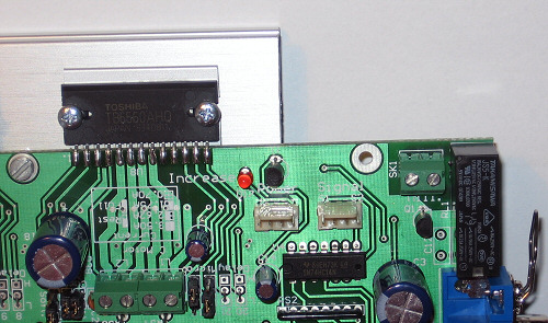
The state of the motor excitation is indicated by a LED with the notice "Increase" ,which can be found on the controller. Its continual lighting means that the motors are running with full excitation. The correct function of the CNC software can be checked by that (during stepping it must always light if the rest function is set by the jumpers [Rest]).
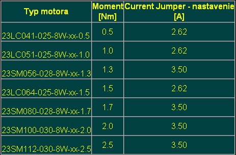
In the course of determination of the motor current to be adjusted, the data-sheet of the motor must always be taken into account. In case of 8-wire (universal) motors 1.5-fold of the nominal coil current must be choosen if the coils are parallel connected (which is recommended). The excitation current must be jumpered by approaching from the higher values. E.g. : if the motor current to be adjusted is 3A, then the Current jumpers must be set to the position of 3.5A. If the current to be adjusted is 2.5A, then the position of 2.62A must be choosen.
Recommended adjustments of the motor current:
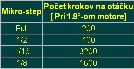
Adjustment of Resolution (micro-step):
The extent of stepping of motors (micro-step) can be adjusted by two 3-level jumpers in the "Micro" jumper field (that can be done for each axis).

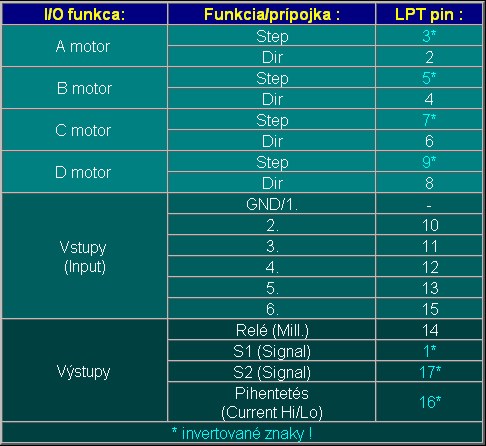
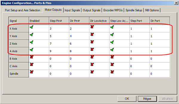
H2 Controller has several inputs and outputs, all of them are monitored and used for different purposes by the applied CNC Control programme. Therefore their task depend how they are set within the programme. Each of the control programmes identifies the inputs and outputs (ports) based upon the pin number of the LPT port belongs to the port. Towards the end of the description there will be a summerising table, which shows the LPT pin-number allocation of the given ports and motors.
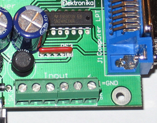
Inputs:
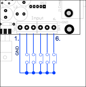
H2 CNC Controller contains 5 inputs. The inputs are available on the Input terminal. Pin 1 of the terminal is GND, the input ports marked 2 - 6 can be operated by switching them to that (No 1) pin.
|

|
The sample circuit presented above supposes the use of Mach3 CNC controlo software, using this software these functions are also available. Further information can be found in the description of the control softwares.
Outputs:
The Controller has two types of outputs:
- Relay output,
- Signal port (2-bit, TTL-type output).
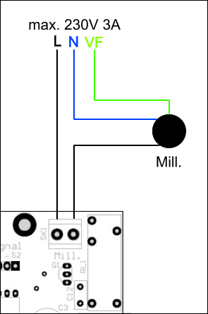
Relay output:
The relay output is potential independent, can be loadad with 3A at maximum 230V. The relay provides one-pole separation. Its pins are available on the Mill. terminal.
|

|
|
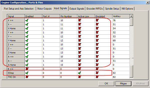
Estop is fixed, but the others can be flexibly handled. The function depends on the configuration (this is just an example among the many possible configurations). The above described adjustment supposes the pins from number 2 to number 6 on the input ports to be end-positions. According to the adjustments:
pin No 2 on the terminal (pin No 10 on LPT) = the parallel connected maximum endpositions of the 4 axes,
pin No 3 on the terminal (pin No 11 on LPT) = the minimum end position of axis X (and that of X Home at the same time),
pin No 4 on the terminal (pin No 12 on LPT) = the minimum end position of axis Y (and that of Y Home at the same time),
pin No 5 on the terminal (pin No 13 on LPT) = the minimum end position of axis Z (and that of Z Home at the same time),
pin No 6 on the terminal (pin No 15 on LPT) = the minimum end position of axis A (and that of A Home at the same time).
Using the above-written adjustment the system is also able to record and search for the automatic 0 point (Home) (even with the co-existance of other adjustments).
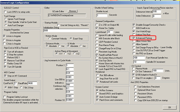
|
|
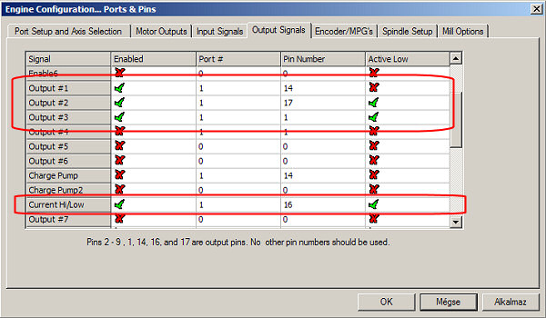
|
The Current Hi/Low is responsible for resting the motors, so its set-up is compulsory. The output No 1 pin controls the relay, its setup is OK. The output No 2 pin and No 3 pin are the bits of the expansion port of S1 and S2, its setup can be handled flexible and there are many possible variations of its setup (PWM, relays, fifth axis, etc.). The knowlidge of the possibilities offered by the software is necessary for their aplication.

- Ak chcete pridať komentáre, tak sa musíte prihlásiť